Question: The following data from the orthogonal cutting test is available. Rake angle = +10°; Chip thickness ratio = 0.35; Uncut chip thickness = 0.51 mm; Width of cut = 3 mm; Yield shear stress of work material = 285 N/mm2; Mean friction co‐efficient on tool face = 0.65. Determine the following forces: [ESE 2000]
- Main cutting force
- Radial force
- Normal force on tool
- Shear force
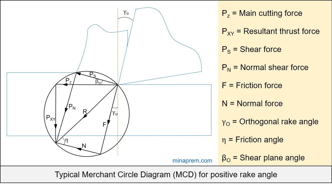
Solution: Force calculation in machining mostly requires help of Merchant Circle Diagram (MCD). MCD is a graphical representation of several forces associated with orthogonal machining with a perfectly sharp cutting tool. It displays shear force (PS), normal shear force (PN), main cutting force (PZ), resultant thrust force (PXY), friction force (F), normal force (N) and a resultant force (R). One characteristics of MCD is that the resultant (R) is the diameter of the circle. A typical Merchant Circle Diagram for a tool having positive orthogonal rake angle is shown below.

Very first requirement to utilize MCD is the knowledge of relevant angles. In general, MCD is associated with tree angles, namely orthogonal rake angle, shear angle and friction angle, as displayed in above diagram. In the question, the orthogonal rake angle is given as +10°. However, other two angles are unknown. The unknown angles can be calculated from their basic formulas. So let us first find out unknown angles.
Step-1: Calculate shear angle (βO)
Given, orthogonal rake angle (γO) = +10°
Chip thickness ratio (rcu) = 0.35
∴ Chip reduction coefficient (ζ) = 1/rcu = 1/0.35 = 2.86
Shear angle in orthogonal machining can be expressed in terms of orthogonal rake angle and chip reduction coefficient as give below. Since both values are known, so shear angle can be calculated easily as illustrated below.
\[\tan {\beta _O} = \frac{{\cos {\gamma _O}}}{{\zeta – \sin {\gamma _O}}}\]
\[\tan {\beta _O} = \frac{{\cos 15}}{{2.86 – \sin 15}} = 0.371\]
\[{\beta _O} = {\tan ^{ – 1}}\left( {0.371} \right) = 20.35^\circ \]
Step-2: Calculate friction angle (η)
Tangent of friction angle (η) gives the co-efficient of friction (μ). In question, the mean friction co‐efficient is given as 0.65. Therefore, the friction angle can be calculated easily as shown below.
\[\mu = \tan \eta \]
\[\eta = {\tan ^{ – 1}}\mu = {\tan ^{ – 1}}\left( {0.65} \right) = 33.02^\circ \]
Step-3: Calculate shear force (PS)
Since all of the three angles (orthogonal rake angle, shear angle and friction angle) are known, so MCD can be utilized effectively. However, to determine any force using MCD, at least one force must be known. Here, no force value is directly given; instead other input in terms of material property and machining data are given. The shear force (PS) can be obtained by multiplying shear strength or yield shear stress of the workpiece material (τS) with shear area (AS). This shear area can again be expressed in terms of uncut chip thickness (a1) and width of cut (b) using the shear angle (βO).
\[{P_S} = {\tau _S}{A_S}\]
\[{P_S} = {\tau _S}\left( {\frac{{{a_1}}}{{\sin {\beta _O}}} \times b} \right)\]
\[{P_S} = 285 \times \frac{{0.51}}{{\sin 20.35}} \times 3\]
\[{P_S} = 1253.9N\]
Step-4: Calculate main cutting force (PZ)
Once one force value is known, all other forces can be calculated with the help MCD simply by using angular relationship. It is convenient to calculate resultant force (R) first, so that no direct formula is required to remember. Consider the right angle triangle made by PS, PN and R. Using cosine relation, R can be calculated from known PS value, as shown below.
\[\cos \left( {{\beta _O} + \eta – {\gamma _O}} \right) = \frac{{{P_S}}}{R}\]
\[R = \frac{{1253.9}}{{\cos \left( {20.35 + 33.02 – 15} \right)}}\]
\[R = 1599.3N\]
Now the main cutting force (PZ) can be calculated using this R value. Consider the right angle triangle made by PZ, PXY and R. The following can be written:
\[\cos \left( {\eta – {\gamma _O}} \right) = \frac{{{P_Z}}}{R}\]
\[{P_Z} = 1599.3 \times \cos \left( {33.02 – 15} \right)\]
\[{P_Z} = 1520.86N\]
Step-5: Calculate radial force (PY)
In order to calculate radial force (PY), first we need to calculate resultant thrust force (PXY). It can be find out easily from the right angle triangle made by PS, PN and R, as given below.
\[\sin \left( {\eta – {\gamma _O}} \right) = \frac{{{P_XY}}}{R}\]
\[{P_{XY}} = 1599.3 \times \sin \left( {33.02 – 15} \right)\]
\[{P_{XY}} = 494.74N\]
Now we need one assumption. The machining is one orthogonal cutting, so the principal cutting edge angle (φ) of the cutting tool can be considered as 0°. The radial force is related to resultant thrust force as shown below.
\[{P_Y} = {P_{XY}}\cos \phi \]
\[{P_Y} = 494.74 \times \cos 90\]
\[{P_Y} = 0\]
Step-6: Calculate normal force on tool (N)
Once again consider the right angle triangle made by F, N and R. Since R value is already known, so N can be calculated easily, as shown below.
\[\cos \eta = \frac{N}{R}\]
\[N = 1599.3 \times \cos 33.02\]
\[N = 1340.98N\]
Now all required values have been calculated. So the answers are:
- Main cutting force (PZ) = 1520.86 N
- Radial force (PY) = 0
- Normal force on tool (N) = 1340.98 N
- Shear force (PS) = 1253.9 N